I really wanted to call this post Five Easy Pieces, but I'm not Jack Nicholson and I only had two simple SKiDL designs to show. So here they are.
LED Clock
DougE recently posted a script that will layout a clock face with 60 LEDs for the minute markers and 12 more LEDs for the hour markers like this:

He also posted his schematic for how the LEDs are interconnected:

Now a repetitive schematic like that just calls out for a SKiDL implementation, so here's what I came up with:
from skidl import *

anodes = Bus('a', 6)    # 6-bit anode bus, but only use a[1]..a[5].
cathodes = Bus('k', 16) # 16-bit cathode bus, but only use k[1]..k[15].

# Create an LED template that will be copied for each LED needed.
led = Part("Device", 'D', footprint='Diodes_SMD:D_0603', dest=TEMPLATE)

# Connect the 60 second LEDs to the anodes and cathodes.
for a in anodes[1:4]:             # Connect LEDs between anodes 1, 2, 3, 4.
    for k in cathodes[1:15]:      # and cathodes 1, 2, 3, ... , 15.
        led()['A', 'K'] += a, k   # Copy LED template and connect anode and cathode.

# Now connect the 12 hour LEDs, all of which are attached to anode a[5].
# The nested for loops select the cathodes in the correct order.
for i in range(2,6):
    for k in cathodes[i:i+10:5]: # Connect k[2,7,12], k[3,8,13], k[4,9,14] and k[5,10,15].
        led()['A', 'K'] += anodes[5], k  # Copy LED and connect anode and cathode.

ERC()               # Look for rule violations.
generate_netlist()  # Generate netlist file.
Saving my skidl script in a file called led_clock.py, I generated a netlist
with the command:
$ python led_clock.py
This stored the netlist into a file called led_clock.net.
I imported the netlist into PCBNEW which arranged the LEDs like this:
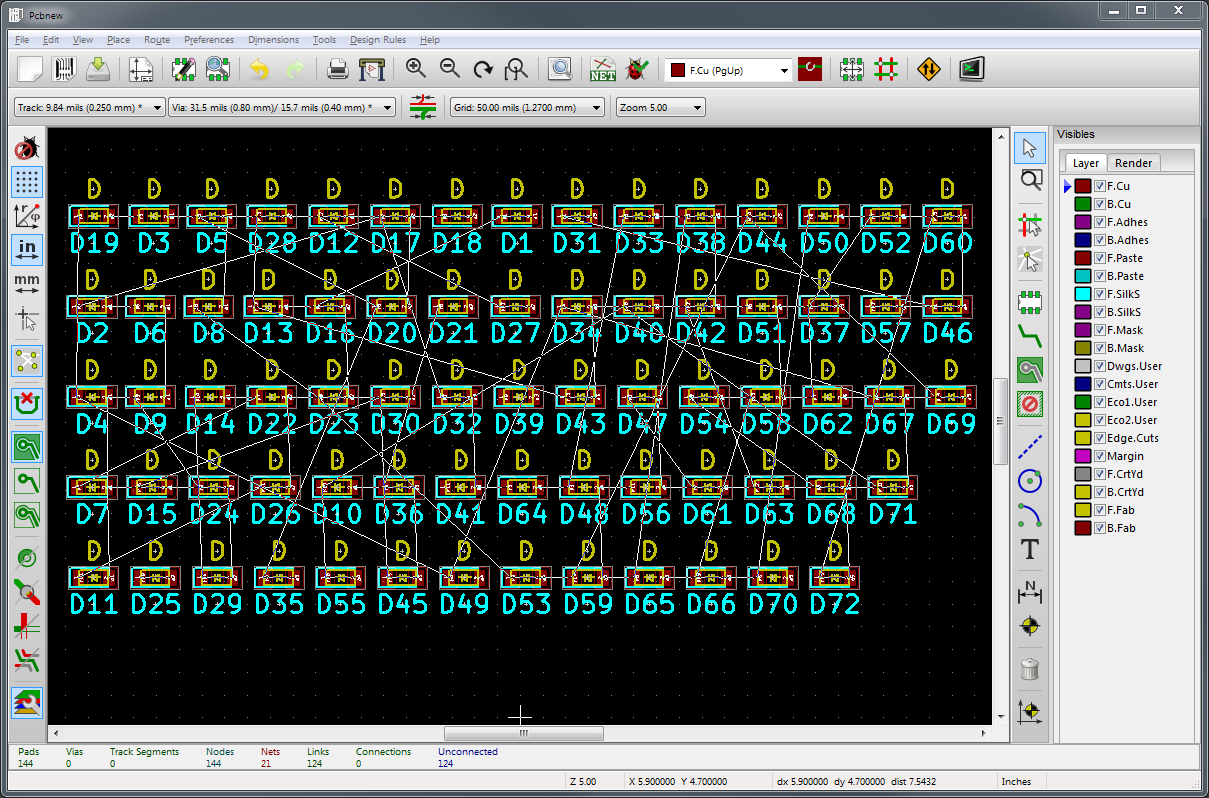
Obviously that doesn't look much like a clock face, but DougE's script should
take care of that.
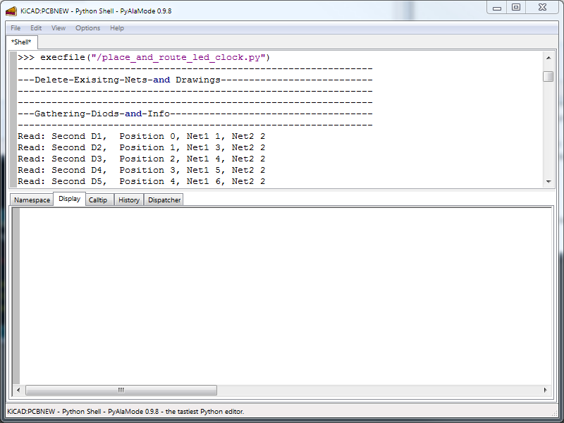
I stored his script in a file called place_and_route_led_clock.py in my top-level
directory, and then executed it in PCBNEW's Python shell:
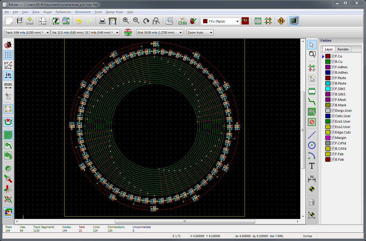
The script rearranged the LEDs and routed all the traces to create a clock face similar to the one above (except mine uses a smaller 0603 LED):
This SKiDL script is relatively simple because it uses only LEDs and the bus sizes are fixed for a particular clock face layout. The next piece shows what happens when a more generalized solution is desired.
VGA Interface
I sell a simple VGA interface that forms a weighted sum of digital signals to create the analog red, green and blue signals which drive a monitor. The guts of the circuit are shown below:
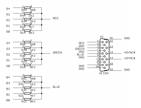
As it stands, this would be simple to implement in SKiDL. But why settle for a VGA interface with the red, green and blue color depths fixed at five bits when I could have a SKiDL script that generates any depth I want! The script shown below does that as follows:
-
The widths of the digital color buses are examined to determine the color depth.
-
Extra bits are added to any of the color buses so they are all the same width.
-
The values of the resistor weights are calculated for the given color depth.
-
The resistors are instantiated using resistor networks, each containing four isolated resistors.
-
The resistors in each network are connected to the appropriate signal in the red, green or blue color bus and the corresponding red, green or blue analog VGA signal.
-
The red, green and blue analog signals and the horizontal and vertical sync signals are connected to a 15-pin VGA connector.
from skidl import *

@SubCircuit
def vga_port(red, grn, blu, hsync, vsync, gnd, logic_lvl=3.3):
    """Generate analog RGB VGA port driven by red, grn, blu digital color buses."""

    # Determine the color depth by finding the max width of the digital color buses.
    # (Note that the color buses don't have to be the same width.)
    depth = max(len(red), len(grn), len(blu))

    # Add extra bus lines to any bus that's smaller than the depth and
    # connect these extra lines to the original LSB bit of the bus.
    for bus in [red, grn, blu]:
        add_width = depth - len(bus)  # Number of lines to add to the bus.
        if add_width > 0:
            bus.insert(0, add_width)  # Add lines to the beginning of the bus.
            bus[add_width] += bus[0:add_width]   # Connect the added bus lines to original LSB.

    ######################################################################
    # Calculate the resistor weights to support the given color depth.
    vga_input_impedance = 75.0  # Impedance of VGA analog inputs.
    vga_analog_max = 0.7        # Maximum brightness color voltage.

    # Compute the resistance of the upper leg of the voltage divider that will
    # drop the logic_lvl to the vga_analog_max level if the lower leg has
    # a resistance of vga_input_impedance.
    R = (logic_lvl - vga_analog_max) * vga_input_impedance / vga_analog_max

    # The basic weight is R * (1 + 1/2 + 1/4 + ... + 1/2**(width-1))
    r = R * sum([1.0/2**n for n in range(depth)])

    # The most significant color bit has a weight of r. The next bit has a weight
    # of 2r. The next bit has a weight of 4r, and so on. The weights are arranged
    # in decreasing order so the least significant weight is at the start of the list.
    weights = [str(int(r * 2**n)) for n in reversed(range(depth))]
    ######################################################################

    # Quad resistor packs are used to create weighted sums of the digital
    # signals on the red, green and blue buses. (One resistor in each pack
    # will not be used since there are only three colors.)
    res_network = Part(xess_lib, 'RN4', footprint='CTS_742C083', dest=TEMPLATE)

    # Create a list of resistor packs, one for each weight.
    res = res_network(value=weights)

    # Create the nets that will accept the weighted sums.
    analog_red = Net('R')
    analog_grn = Net('G')
    analog_blu = Net('B')

    # Match each resistor pack (least significant to most significant) with
    # the the associated lines of each color bus (least significant to
    # most significant) as follows:
    #    res[0], red[0], grn[0], blu[0]
    #    res[1], red[1], grn[1], blu[1]
    #    ...
    # Then attach the individual resistors in each pack between
    # a color bus line and the associated analog color net:
    #    red[0] --- (1)res[0](8) --- analog_red
    #    grn[0] --- (2)res[0](7) --- analog_grn
    #    blu[0] --- (3)res[0](6) --- analog_blu
    #    red[1] --- (1)res[1](8) --- analog_red
    #    grn[1] --- (2)res[1](7) --- analog_grn
    #    blu[1] --- (3)res[1](6) --- analog_blu
    #    ...
    for w, r, g, b in zip(res, red, grn, blu):
        w[1,8] += r, analog_red   # Red uses the 1st resistor in each pack.
        w[2,7] += g, analog_grn   # Green uses the 2nd resistor in each pack.
        w[3,6] += b, analog_blu   # Blue uses the 3rd resistor in each pack.
        w[4,5] += NC, NC   # Attach the unused resistor in each pack to no-connect nets to suppress ERC warnings.

    # VGA connector outputs the analog red, green and blue signals and the syncs.
    vga_conn = Part('conn', 'DB15_FEMALE_HighDensity_MountingHoles', footprint='XESS:DB15-HD-FEMALE')

    vga_conn[5, 6, 7, 8, 9, 10] += gnd  # Ground pins.
    vga_conn[4, 11, 12, 15]     += NC   # Unconnected pins.
    vga_conn[0]  += gnd                 # Ground connector shield.
    vga_conn[1]  += analog_red          # Analog red signal.
    vga_conn[2]  += analog_grn          # Analog green signal.
    vga_conn[3]  += analog_blu          # Analog blue signal.
    vga_conn[13] += hsync               # Horizontal sync.
    vga_conn[14] += vsync               # Vertical sync.
The vga_port subcircuit is combined
with some connectors to build the complete VGA interface circuit:
# Define some nets and buses.

gnd = Net('GND')    # Ground reference.
gnd.drive = POWER

# Five-bit digital buses carrying red, green, blue color values.
red = Bus('RED', 5)
grn = Bus('GRN', 5)
blu = Bus('BLU', 5)

# VGA horizontal and vertical sync signals.
hsync = Net('HSYNC')
vsync = Net('VSYNC')

xess_lib = r'C:\xesscorp\KiCad\libraries\xess.lib'

# Two PMOD headers and a breadboard header bring in the digital red, green,
# and blue buses along with the horizontal and vertical sync.
# (The PMOD and breadboard headers bring in the same signals. PMOD connectors
# are used when the VGA interface connects to a StickIt! motherboard, and the
# breadboard header is for attaching it to a breadboard.
pm = 2 * Part(xess_lib, 'PMOD-12', footprint='XESS:PMOD-12-MALE', dest=TEMPLATE)
bread_board_conn = Part('conn', 'CONN_01x18', footprint='Pin_Headers:Pin_Header_Straight_1x18_Pitch2.54mm')

# Connect the digital red, green and blue buses and the sync signals to
# the pins of the PMOD and breadboard headers.
hsync  += bread_board_conn[1],  pm[0]['D0']
vsync  += bread_board_conn[2],  pm[0]['D1']
red[4] += bread_board_conn[3],  pm[0]['D2']
grn[4] += bread_board_conn[4],  pm[0]['D3']
blu[4] += bread_board_conn[5],  pm[0]['D4']
red[3] += bread_board_conn[6],  pm[0]['D5']
grn[3] += bread_board_conn[7],  pm[0]['D6']
blu[3] += bread_board_conn[8],  pm[0]['D7']
red[2] += bread_board_conn[9],  pm[1]['D0']
grn[2] += bread_board_conn[10], pm[1]['D1']
blu[2] += bread_board_conn[11], pm[1]['D2']
red[1] += bread_board_conn[12], pm[1]['D3']
grn[1] += bread_board_conn[13], pm[1]['D4']
blu[1] += bread_board_conn[14], pm[1]['D5']
red[0] += bread_board_conn[15], pm[1]['D6']
grn[0] += bread_board_conn[16], pm[1]['D7']
blu[0] += bread_board_conn[17]

# The VGA interface has no active components, so don't connect the PMOD's VCC pins.
NC     += pm[0]['VCC'], pm[1]['VCC']

# Connect the ground reference pins on all the connectors.
gnd    += bread_board_conn[18], pm[0]['GND'], pm[1]['GND']

# The PMOD ground pins are defined as power outputs so there will be an error
# if they're connected together. Therefore, turn off the error checking on one
# of them to swallow the error.
pm[1]['GND'].do_erc = False

# Send the RGB buses and syncs to the VGA port circuit.
vga_port(red, grn, blu, hsync, vsync, gnd)

ERC()                # Run error checks.
generate_netlist()   # Generate the netlist.
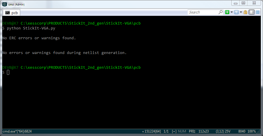
Then it's just a matter of running the script:
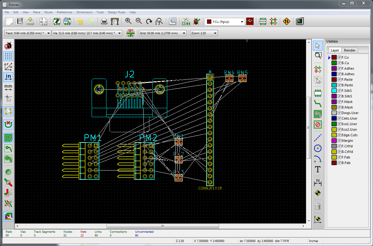
And then importing the netlist into PCBNEW:
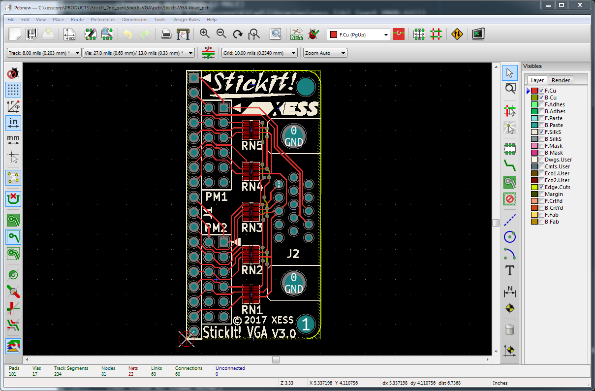
After the tedious work of placing parts and routing wires, the final VGA interface PCB layout appears:
Now, you could say this SKiDL script doesn't qualify as an "easy piece". There are some complications in the code, but that's what usually happens when you try to make a program less specific and more general. Making the script handle color buses with arbitrary and non-uniform sizes necessarily leads to the use of iterative loops and arcane code for handling edge cases. But once that's done, it's done: I never have to design that circuit again (as I've done a number of times over the years). I just call the script when I need a VGA interface and it handles all the details. In effect, the SKiDL script is a smart module that encapsulates the design intent for not just one circuit, but for an entire family of circuits. And anyone else can use it in their designs, similar to how programmers insert calls to subroutine libraries into their code.
