It helps when other people use SKiDL; then I can coast by just showing what they've done. Here are two examples.
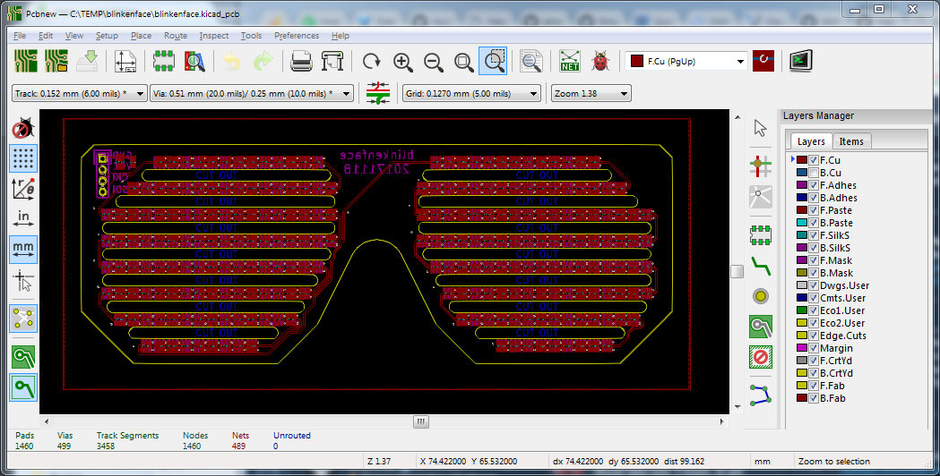
Blinkenface
Blinkenface is a version of "LED glasses" made with a cascaded string of APA102 RGB LEDs controlled through an SPI interface:

Th majority of Blinkenface is just a repetitive connection of one APA102 to the next one in line: perfect for a loop construct! And that's just what's done in the associated SKiDL code:
#!/usr/bin/python

import skidl

skidl.lib_search_paths[skidl.KICAD].append('gsg-kicad-lib')

gnd = skidl.Net('GND')
vcc = skidl.Net('VCC')

num_leds = 242
leds = []
sdo = []
cko = []
for i in range(num_leds):
    leds.append(skidl.Part('gsg-symbols.lib', 'APA102', footprint='gsg-modules:APA102-2020'))
    sdo.append(skidl.Net('SDO' + str(i)))
    cko.append(skidl.Net('CKO' + str(i)))
    leds[i]['SDI'] += sdo[i]
    leds[i]['CKI'] += cko[i]
    leds[i]['GND'] += gnd
    leds[i]['VCC'] += vcc
    # connect input to previous output
    if 0 < i:
        leds[i-1]['SDO'] += sdo[i]
        leds[i-1]['CKO'] += cko[i]

# don't connect the output of the last LED
leds[-1]['SDO'] += NC
leds[-1]['CKO'] += NC

# connect the input of the first LED to a pin header
header = skidl.Part('conn', 'CONN_01X04', footprint='gsg-modules:HEADER-1x4')
header[1] += gnd
header[2] += vcc
header[3] += cko[0]
header[4] += sdo[0]

# assume that power is applied to pin header
header[1].net.drive = skidl.POWER
header[2].net.drive = skidl.POWER

decoupling_caps = []
decoupling_caps.append(skidl.Part("Device", 'C', footprint='gsg-modules:0805'))
decoupling_caps.append(skidl.Part("Device", 'C', footprint='gsg-modules:0603'))
for i in range(2):
    decoupling_caps[i][1] += vcc
    decoupling_caps[i][2] += gnd

skidl.ERC()
skidl.generate_netlist()
The code probably isn't as compact and "Pythonic" as it could be because -- as the designer admits -- they're not Python experts. And that's an important feature of SKiDL: regardless of your skill level, you can still get the job done. And this gets the job done by connecting 242 LEDs in just 50 lines of code.
SPIDriver
The next example is an actual product: the SPIDriver!
The SPIDriver has a more conventional topology than the previous example, consisting of a microcontroller, display, USB interface, and headers. The SKiDL code is partitioned into sections for each major component:
from skidl import *

def bypass(sig, val = '0.1uF'):
    c1 = Part("Device", 'C', value = val, footprint = 'Capacitors_SMD:C_0402')
    c1[1] += sig
    c1[2] += gnd

def divider(ratio, hi, low, res):
    r1 = Part("Device", 'R', value = '500K', footprint = 'Resistors_SMD:R_0402')
    r2 = Part("Device", 'R', value = '500K', footprint = 'Resistors_SMD:R_0402')
    r1[1] += hi
    r1[2] += r2[1], res
    r2[2] += low

gnd = Net('GND')  # Ground reference.

v5 = Net('5V')
v5b = Net('5VB')
v33a = Net('3.3V')
v33b = Net('3.3VB')

u1 = Part('silabs2', 'EFM8BB10F8G-A-QFN20', footprint = 'Housings_DFN_QFN:SiliconLabs_QFN-20-1EP_3x3mm_Pitch0.5mm_ThermalVias')
u2 = Part('ftdi', 'FT232RL', footprint = 'Housings_SSOP:SSOP-28_5.3x10.2mm_Pitch0.65mm')
u3 = Part('regul', 'AP1117-15', footprint = "TO_SOT_Packages_SMD:SOT-223-3Lead_TabPin2")
u4 = Part('linear', 'ZXCT1110', footprint = 'TO_SOT_Packages_SMD:SOT-23-5')

j1 = Part('conn', 'USB_OTG', footprint = 'Connectors_USB:USB_Micro-B_Molex_47346-0001')
j2 = Part('conn', 'Conn_01x04_Male', footprint = 'Pin_Headers:Pin_Header_Angled_1x04_Pitch2.54mm')
j3 = Part('conn', 'Conn_01x06_Male', footprint = 'Pin_Headers:Pin_Header_Angled_1x06_Pitch2.54mm')
j4 = Part('conn', 'Conn_01x06_Male', footprint = 'Pin_Headers:Pin_Header_Angled_1x06_Pitch2.54mm')

d1 = Part('adafruit', 'JD-T1800', footprint = 'JD-T1800')

################## U1: MCU       ##################

v33a += u1.pin('VDD')
gnd += u1['^GND$']
divider(2.4 / 6, v5, gnd, u1['P1.5'])
resetpullup = Part("Device", 'R', value = '1K', footprint = 'Resistors_SMD:R_0402')
resetpullup[1] += u1.pin('RSTb/C2CK')
v33a += resetpullup[2]

################## U2: FTDI      ##################

v5  += u2.pin('VCC')
v33a += u2.pin('VCCIO')
v33a += u2.pin('3V3OUT')
gnd += u2['^GND$']
gnd += u2.pin('AGND')
gnd += u2.pin('TEST')
u2['RXD'] += u1.pin('P0.4')
u2['TXD'] += u1.pin('P0.5')
NC += u2['RTS,CTS,DTR,DCR,DCD,RI,CBUS?,OSC[IO],~RESET~']

################## J1: USB       ##################

gnd += j1.pin('GND'), j1.pin('Shield')
v5 += j1.pin('VBUS')
NC += j1['ID']

################## U3: regulator ##################

gnd += u3.pin('GND')
v5b += u3.pin('VI')
v33b += u3.pin('VO')

################## U4: current sensor #############

rsense = Part("Device", 'R', value = '.1', footprint = 'Resistors_SMD:R_0805')
rgain = Part("Device", 'R', value = '2K4', footprint = 'Resistors_SMD:R_0402')
rgain[1] += u4.pin('OUT'), u1['P1.6']
rgain[2] += gnd
v5 += u4.pin('Vs+'), rsense[1]
v5b += rsense[2], u4.pin('Vs-'), j3[5:6]
gnd += u4.pin('GND')
NC += u4.pin('NC')

################## J2: debug     ##################

j2[1] += v33a
j2[2] += gnd
j2[3] += u1.pin('P2.0/C2D')
j2[4] += u1.pin('RSTb/C2CK')

################## J3: power out ##################

gnd += j3[1:2]
v33b += j3[3:4]

################## J4: signal out ##################

j4[1] += u1.pin('P0.0') # SCK
j4[2] += u1.pin('P0.1') # MISO
j4[3] += u1.pin('P0.2') # MOSI
j4[4] += u1.pin('P0.3') # CS
j4[5] += u1.pin('P0.6') # A
j4[6] += u1.pin('P0.7') # B

################## D1: display   ##################

gnd += d1['GND']
u1['P1.0'] += d1['CLOCK']
u1['P1.[12]'] += d1['DATA']
u1['P1.3'] += d1['CS']
u1['P1.4'] += d1['RS/DC']
v33a += d1['LEDA']
ledres = Part("Device", 'R', value = '22', footprint = 'Resistors_SMD:R_0402')
ledres[1] += d1['LEDK']
gnd += ledres[2]
v33a += d1['RESET']
v33a += d1['VCC']

# tp1 = Part('conn', 'TEST_1P')
# tp1.footprint = 'Measurement_Points:Measurement_Point_Round-SMD-Pad_Small'

def conn(*pins):
    q = Net()
    q += pins

conn(j1.pin('D+'), u2.pin('USBD+'))
conn(j1.pin('D-'), u2.pin('USBD-'))

bypass(v33a)            # MCU (datasheet 5.1)
bypass(v33a, '1uF')
bypass(v33a)            # FTDI
bypass(v5)
bypass(v5, '10uF')
bypass(v33b)

if 0:
    r1, r2 = 2 * Part("Device", 'R', TEMPLATE)  # Create two resistors.
    r1.value, r1.footprint = '1K',  'Resistors_SMD:R_0805'  # Set resistor values
    r2.value, r2.footprint = '500', 'Resistors_SMD:R_0805'  # and footprints.
    r1[1] += vin      # Connect the input to the first resistor.
    r2[2] += gnd      # Connect the second resistor to ground.
    vout += r1[2], r2[1]  # Output comes from the connection of the two resistors.

ERC()

generate_netlist()
I will confess I'm somewhat mystified by this code.
It uses a method for a Part called pin() like this:
gnd += u3.pin('GND')
This connects the ground pin of the power regulator to ground. But I would have written that as:
gnd += u3['GND']
In fact, my version of SKiDL doesn't even have a method called pin()
associated with a Part object.
Probably this was done to add some capability or remove some flaw that wasn't
readily noticeable to anyone but the designer.
So this highlights another feature of SKiDL: since it's open source, you can modify it to do
whatever you want.
Any way, these are two examples of using SKiDL that weren't done by me. If you have used SKiDL for something, drop me a line and let me know.
