After installing my PYNQ board, I took a break to release an update to my SKiDL circuit design language. These things always take longer than you expect, but I’m back now and my next task is to familiarize myself with the PYNQ documentation.
When you first login to the PYNQ, you’ll see the getting_started link:
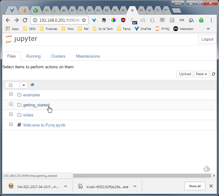
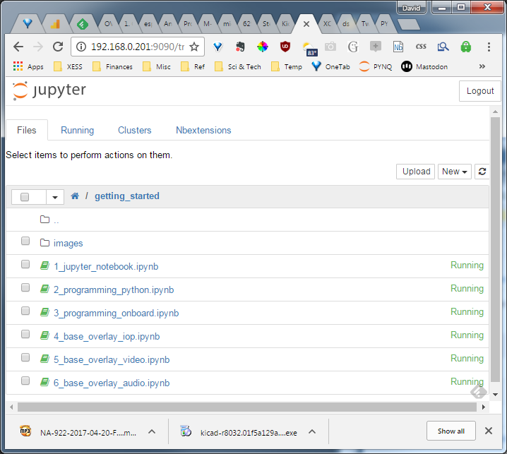
Clicking on that (because that seems a natural place to start) brings up a set of introductory Jupyter notebooks:
The first thing you need to realize about these notebooks is you can skip all of them! If you’re like me and have to read everything out of fear you’ll miss something, know that all this material is already available at the main PYNQ documentation site.
However, one advantage of having these notebooks immediately available upon setting up the PYNQ is that you can exercise the board without having to download anything. Here’s what the notebooks cover:
-
1_jupyer_notebook.ipynb: Explains the basics of getting around in a Jupyter notebook. -
2_programming_python.ipynb: Gives a brief introduction to Python, but you’ll want to take advantage of the many online Python tutorials to get a full understanding. (This is probably a good idea, just like learningCwas a good idea in the 80’s.) -
3_programming_onboard.ipynb: Let’s you play with the buttons, slide switches and LEDs of the PYNQ. Every system has a blinky, and this one is PYNQ’s. -
4_base_overlay_iop.ipynb: Shows you how to access the Pmod ports to sense the ambient light level and display it on an OLED. Of course, if you don’t have the light sensor or OLED PMODs then this is pretty much useless. -
5_base_overlay_video.ipynb: Demonstrates capturing and displaying video via the two HDMI ports on the PYNQ. There’s also a bit of image processing. -
6_base_overlay_audio.ipynb: Like the video demo, but using the on-board microphone (it’s actually a tiny chip on the underside of the board) and an external speaker or headphones to record and playback sound.
Turning to the main PYNQ site, here are the nuggets I extracted:
-
PYNQ uses the ZYNQ chips’s processing system (PS) with dual ARM processors to run the Jupyter notebook and Python interpreter.
-
The programmable logic (PL) section is used to host overlays.
-
An overlay programs the PL to provide support for an application. An API allows the PS to load overlays into the PL and access functions in it such as read and write registers. The API is contained in a Python module and accessed with Python.
-
Creating an overlay is done using the Vivado FPGA programming environment and requires logic design expertise. To leverage this limited expertise, an overlay is typically designed with maximum generality so it can be used in a large number of applications. For example, the base overlay provides functions for working with the Pmod and Arduino I/O interfaces, audio I/O, HDMI I/O, and general-purpose I/O.
-
The Arduino and Pmod connectors can interface to a wide variety of external circuitry. In order to support this without having to redesign the logic circuitry for each application, the base overlay uses reprogrammable I/O Processors (IOPs), a set of peripherals (timers, SPI, I$^2$C, interrupt controllers), and a reconfigurable switch.
-
The IOP is programmed in C/C++ and is intended for real-time, low-level operations. The PS is programmed with Python for higher-level, data-handling and display operations.
-
The base overlay uses a 32-bit, 100 MHz Microblaze for each IOP. A 64 KB dual-port BRAM stores the program for the Microblaze. The PS loads the program into the BRAM and starts the Microblaze. The remainder of the BRAM can be used for local data or for passing data back-and-forth between the PS and the IOP. A mailbox located between
0xF000and0xFFFFin the IOP BRAM is typically used for passing data. The IOP also has access to the external DDR chip on the PYNQ board, and this can be used to transfer larger blocks of data. -
The reconfigurable switch in the IOP allows it to connect its various peripherals to the physical I/O pins of the Pmod or Arduino headers. The switch is controlled by the Microblaze.
-
Programs for the IOP are developed using the Xilinx SDK. Version 2016.1 of Vivado and the SDK is recommended. (I’m currently using 2016.4, so I’ll continue with that until a problem arises.)
-
Building an application for an IOP requires:
-
A hardware description file (HDF) that Vivado uses to create a Hardware Platform. (Already provided for the PYNQ.)
-
A board support package (BSP) that contains the software for interacting with the peripherals described in the HDF. There can be more than one BSP for a hardware platform. For example, the base overlay has two BSPs: one for the Pmod IOP and another for the Arduino IOP.
-
The BSP is linked with the application C/C++ code by the SDK compiler to create an
.elffile which is then translated into a.binfile that can be loaded into the IOP program memory.
-
-
The IOP has an API for interfacing to its peripherals, its reconfigurable switch, and the IOP-to-PS mailbox. (The PS has a separate API for communicating with the IOP.) The Arduino and Pmod IOPs are identical except for the reconfigurable switches that connect their peripherals to the I/O pins of the Arduino or Pmod headers.
-
The details of programming the IOP are explained here. This covers the details of using the IOP
CAPI to talk to the peripherals and reconfigurable switch, and also covers the C and Python APIs for mailbox communications. (I won’t summarize this further. The link will provide a path to the details needed to do IOP programming.) -
Interrupt architecture:
-
The IOPs use the Microblaze AXI Interrupt Controller internally.
-
The base overlay also has an interrupt controller that can throw interrupts from the IOPs over to the PS.
-
One way the interrupts from the IOPs are handled in the PS is with Python’s asyncio package.
-
-
Creating Overlays:
-
Unlike a standard Zynq design, PYNQ’s PS section is already defined and the PL design must match its settings (e.g., clock configuration).
-
Vivado exports a
tclfile describing the application mapped into the PL. Thetclfile is parsed by the PS using theOverlayclass of thepynqPython package. The result of the parsing is a list of addressable resources in the overlay such as interrupt controllers, GPIO pins, IOP BRAMs, etc. -
The
pynqpackage provides theMMIOclass which is used to do memory-to-memory transfers between the PS and the addressable elements of an overlay.
-
After reviewing the PYNQ docs, I see three levels for using the PYNQ, each level requiring the skills of the ones above it:
-
You can be given an overlay and then control it from Python as if it were a peripheral attached to the PS. This requires understanding of the
pynqPython package. -
You can be given an overlay but run your own programs on any IOPs it contains. This requires additional skills to:
-
develop programs for the IOPs (Microblaze programming with the SDK or otherwise),
-
create an API in Python for talking to the IOPs from the PS, and
-
package, download and initiate the compiled programs to the IOPs.
-
-
Develop your own overlay for the PL using Vivado.
So my job now is to progress through these levels.